


Photos of the Kart (3)
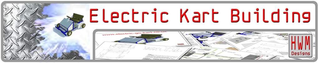
The go kart steering wheel is made from sheet aluminium with the profile created using car body filler before being bound in cycle handlebar tape.
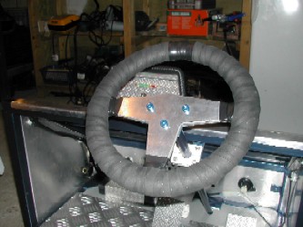
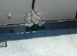
Top and bottom steering column mounts are made from PTFE mounted on welded brackets. The top mount can be seen in the photo (above right).
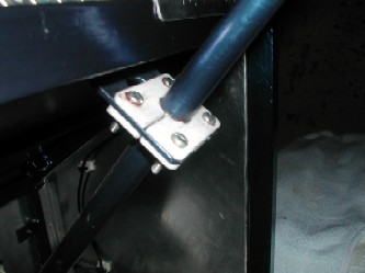
Viewing the kart from underneath the steering linkages can be seen. Ackerman steering is achieved by the offset mounting of the track rod ends on the pitman arm mounted at the bottom of the steering column. In this photo the brake cable outer (blue) is also visible.
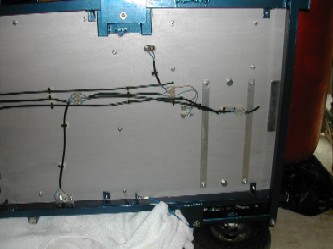
In this view the wiring layout for the lighting and motor control systems can be seen. A switch fitted to the brake cable closes the circuit to the brake light when the brake pedal is pressed.
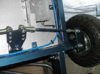
 This is a useful design feature when younger drivers are operating the kart because you can see whether they are actually
pressing the brake pedal when you shout "stop"!
This is a useful design feature when younger drivers are operating the kart because you can see whether they are actually
pressing the brake pedal when you shout "stop"!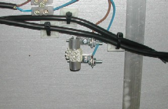 A colour-change LED is fitted on the underside of the floorpan. When driven at night with the colour change LED switched on a ghostly glow emerges from
under the kart. Simple clamp connectors hold the LED in place.
A colour-change LED is fitted on the underside of the floorpan. When driven at night with the colour change LED switched on a ghostly glow emerges from
under the kart. Simple clamp connectors hold the LED in place.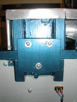
In this picture the underside of the motor mount assembly can be seen. The motor mount fits over the left-hand frame rail and is held in place by a clamping plate that picks up on brackets fitted to the motor mount and rail.